Salvaging a Brother printer’s LCD
I’ve recently acquired a few printers for salvaging the stepper motors out of them. In taking one apart (specifically a Brother MFC-5860CN), I found that the LCD had a 6 pin ribbon cable connected to it. I figured it wouldn’t be too hard to figure out the communication protocol and talk to it so I gave it a shot. Well it wasn’t too hard, but it did take some time and effort.
I picked up an Open Workbench Logic Sniffer from SeeedStudio. This is a pretty useful tool for the price. I had only seen someone work with a logic analyzer before so I had to do some learning before I could start to use it. If you end up getting one, I found this page to be a pretty good documentation hub. I also watched some youtube videos about how to use it which were only somewhat helpful.
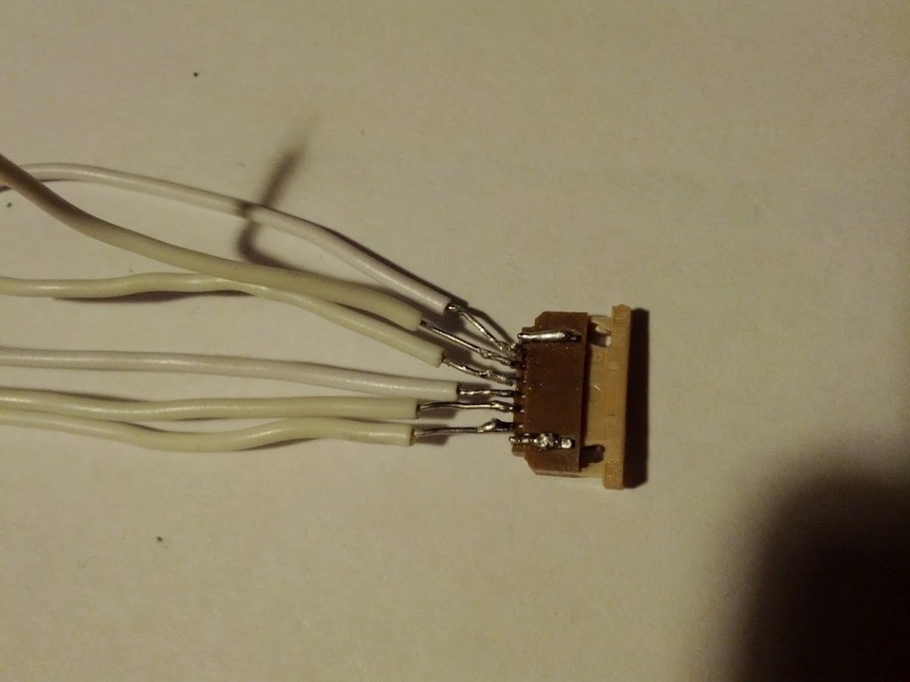
After acquiring a passing knowledge of how to use the logic analyzer, I needed a way to get to the logic signals from the tiny connector. So… this happened:
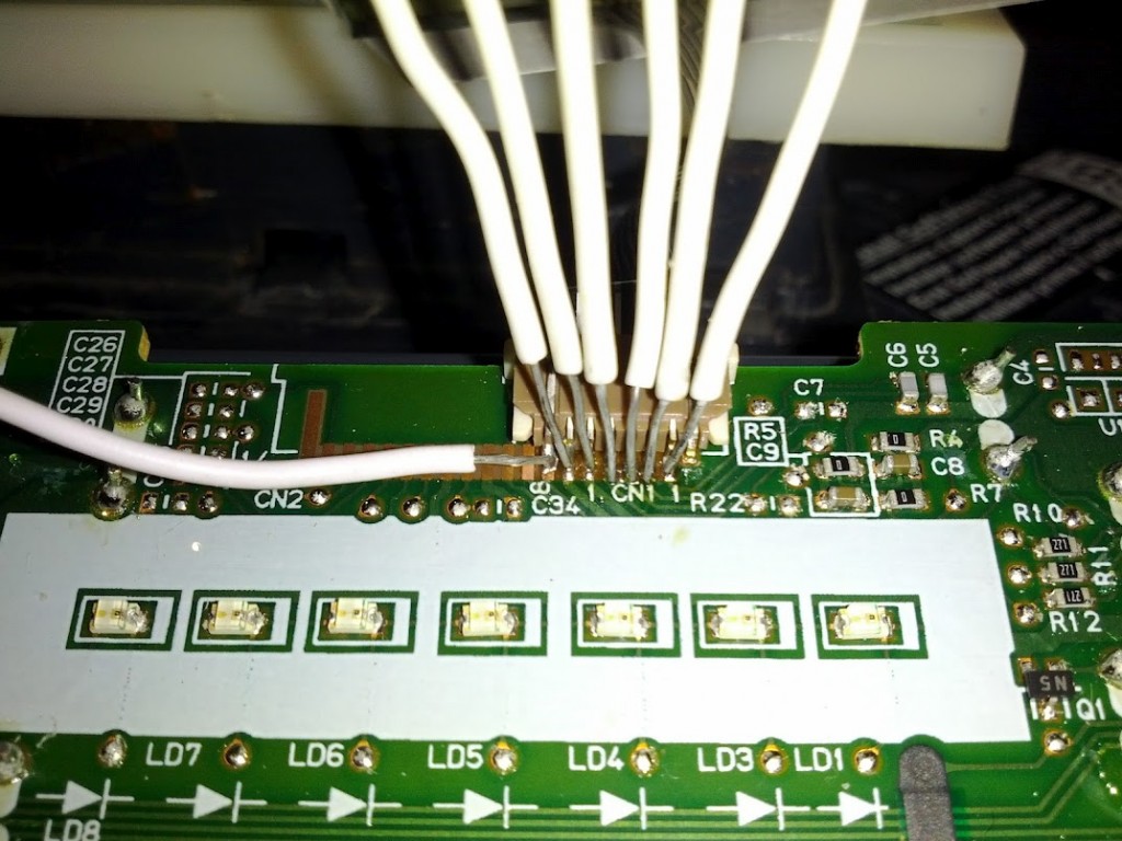
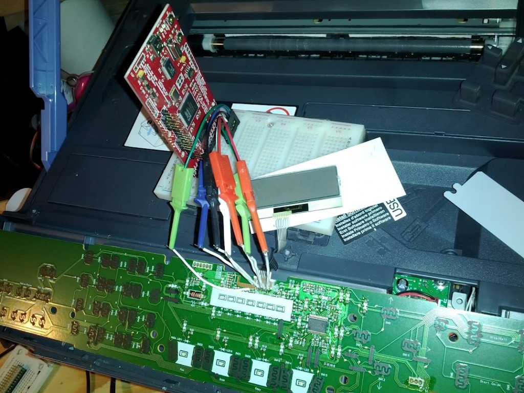
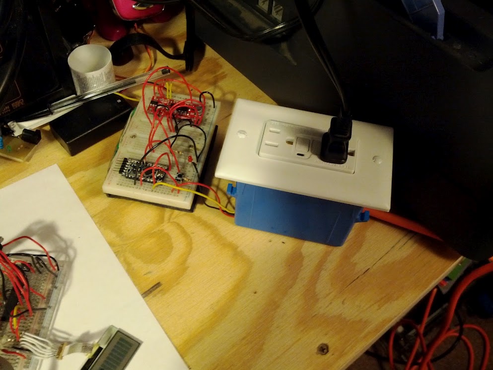
This wasn’t as hard as it could have been, but was still pretty hard especially since some of the wires fell off several times and I had to re-solder them in between the other wires without accidentally desoldering the other wires. And then, I attached some wire clippies to the wires above and to a breadboard where my logic analyzer was plugged in:
Great, so everything was plugged in and ready to figure out. But what exactly was I trying to figure out:
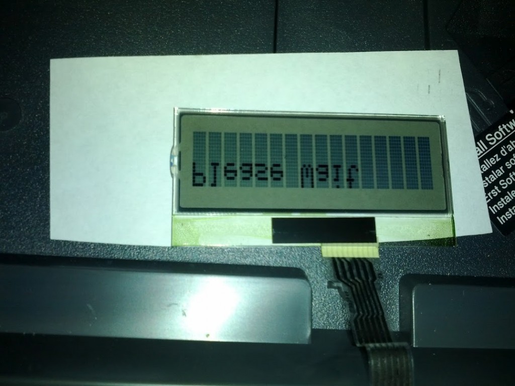
In case you can’t read upside down and backwards, it says “Please Wait”. I needed to figure out how it was sending those words over the 6 wires that the LCD was connected with. So then I connected my logic analyzer to my computer and started capturing data. The logic analyzer only captures logic for a short window of time, and the message seen above only appears on the screen for about 2 seconds so I had to be quick and precise. I would plug the printer in, then wait a second or so, and then hit capture on the logic analyzer software. This was not easy. After struggling for about an hour I finally got something that looked like the data I was looking for, but I wasn’t sure.
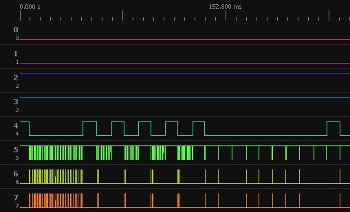
The logic analyzer software has options to analyze I2C, SPI, and a bunch of other types of logic. I was pretty sure that it was either I2C or SPI, but I didn’t know which one, and I didn’t know enough about either one to figure it out. I was finally to the point in my electronics hobbiest career where I had to learn I2C and SPI. I had a feeling that it was using I2C so I started with that.
A quick Google search of “I2C” lead me to this tutorial, and after a bit of reading I felt I had a pretty good understanding of the bus. Since I felt like the data was I2C, I decided to wait on learning the SPI bus. However looking back at and analyzing the logic capture file that I had saved, I realized that the software wasn’t analyzing the data as anything readable and there was a mysterious line that would go logic low when the data was sent. It was time to stop being lazy and learn SPI (which, in the end, wasn’t really that difficult).
Another quick Google search of “spi tutorial” lead me to a couple of tutorials (first one, second one). Turns out that mysterious line that would go logic low when data was sent was the slave select line. Plugging what I learned into the logic analyzer software and tweaking the settings a bit led me to a really geeky point in my life. I saw the following on the screen and was more excited than I’d like to admit:
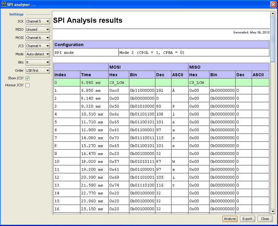
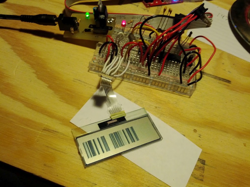
“Please Wait” it said. I had learned the language of the LCD. It was using SPI! Now it was time to rig up my arduino to talk to the LCD. So then I did this:
Don’t worry, this isn’t the same connector from before that I soldered wires to for use with the logic analyzer (you were worried weren’t you). Luckily I had a similar Brother printer that used the same LCD and connector. I desoldered the connector from that printer very carefully since it’s mostly made of plastic and plastic tends to melt when you poke it with a soldering iron. Then I soldered on some wires and plugged it in to a breadboard with a 16MHz/5v Arduino pro mini on it. And then, I wrote some code using the SPI library to recreate what I was seeing on the logic lines. And then, I wired everything up and uploaded the code… And then it didn’t work.
My best guess was that, even though I was dividing the clock frequency by 128, 125kHz (16MHz / 128) was just too fast for the little LCD. hrm. Measuring the wavelength of the clock signal in the logic analyzer software showed me that the printer was sending data at 33kHz-ish. I had a 4.096MHz crystal lying around which, with the same setup, would get me to 32kHz. Close enough. I busted out my DIP Atmega328P, wired it up with the crystal, wired it to my Pocket Programmer, plugged it in, tried to program it, remembered that for some reason the pocket programmer only works with the old version of the arduino software, opened arduino version 22, sucessfully programmed the Atmega, and… no luck. Now I was really confused.
My best guess now was that I missed something when looking at the logic. Maybe there was something required at start up for the LCD to work. But I wasn’t about to try and get the timing perfect by plugging in the printer manually and manually clicking capture. That was ridiculous last time, and it took way too long to find the window of logic where the communication was happening. If I tried that method again, frustration and anger would happen, and something might be destroyed. I previously had an idea that I could use my controllable power outlet and some Java code to automate the process of plugging the printer in and pressing the capture button on the logic analyzer software.
I figured I could use some keyboard simulation to press the enter key with focus on the capture button, and that didn’t turn out to be very hard at all. I found that Java’s Robot class made it really easy to simulate the enter key being pressed. Now I needed to figure out how to connect to a device on a COM port, and read from it. This device would be an arduino connected to my controllable power outlet. However, doing this in Java turned out to be not so easy. In fact, apparently this is no longer supported in Java. That sucks. Now what to do.
I’d heard of people connecting to their arduinos using Python, but before I could try that I had to relearn Python. The version of Python for windows comes with a very in depth help tutorial, which I read for a couple of hours. Once I was familiar enough to do some basic tasks I started diving into python libraries. I quickly found PySerial (download) which would make it relatively easy to connect to a COM port and do read/write operations. Then after looking through a couple of other libraries I found one that would do keyboard simulation (tutorial).
I combined some proof of concept python scripts and created a script that would allow you to specify waiting times (in milliseconds) for the turning on of the power outlet and the pressing of the enter button. By changing these times (mostly just the power outlet time) I was able to capture data from right after the printer was turned on. There ended up being nothing really useful there, however I kept playing and found a set of wait times that would capture the beginning of the data transmission (which I had seen before when I found it manually). Looking more closely at this logic, I found a sequence of numbers (13, 72 ,9) being sent before each transmission. When I uploaded the program with this sequence of numbers at the beginning of the transmission and did some rewiring it said “Hi”.
I had done it! I successfully reverse engineered the LCD. I turned it on and off a couple of times, dragged my wife over to show her my accomplishment, and then realized that there was something wrong. Occasionally when I turned it on, the letters would smear down so that there were ugly lines showing on the screen instead of the text that was supposed to be showing. It was great that I had figured out how to make something show on the screen, but I wasn’t finished. This project was not complete (are you tired of reading yet?).
My first guess this time was that there was noise in the lines and I needed some filtering caps. After looking at the PCB from the printer, I found that there were some capacitors on there that I had missed when recreating the circuit. So then, I measured the values with a multimeter and found some lying around that had the same value. But inserting these capacitors into my circuit did not fix the problem.
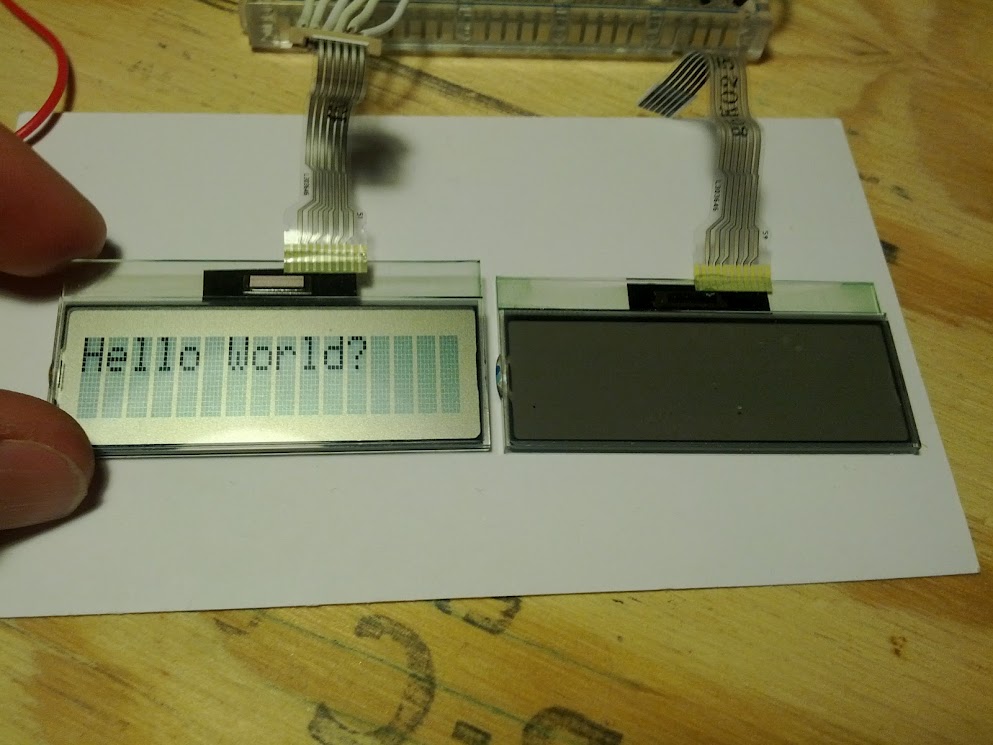
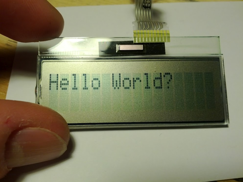
In my original measurements to figure out the ground and power lines of the LCD, I had found that there were 2 lines that read as 5v which were pin 1 and pin 3. I had previously noticed that with only pin 1 connected to 5v the LCD would not work at all, so I had connected pins 1 and 3 together so that they were both at 5v. This was my current setup. I tried the only other option of connecting only pin 3 to 5v, and voila!, the LCD was turning on and printing the text (now “Hello World?”) every time. However, the screen was much more dim than it was when it had occasionally worked with the previous setup.
I was starting to get the idea that pin 1 was the contrast pin, and, after testing my theory by plugging pin 1 into my 5v line on my breadboard after the text was already showing, I found that to the best of my knowledge that pin 1 was indeed a contrast pin. So now my idea was that I needed to pull pin 1 high after the text was already being displayed. I wired pin 1 to pin 12 on my ATMega chip (arduino pin 6) and rewrote my program to turn on pin 6 after the text was being displayed. At this point I’m feeling like I should be really close to just stomping on the whole thing if it doesn’t work. It didn’t work (however it was surprisingly not that frustrating).
I had one last idea to try before I was ready to quit and write this project off as beyond my current knowledge. There were periods of hundreds of milliseconds that I had not seen in the logic. It was time to stop taking shortcuts and just figure the whole thing out, so I, once again, got out my controllable power outlet setup, and started precisely writing down everything that I saw in the logic. What I found (from my notes):
vcc goes high
<1ms passes
contrast goes high
133ms pass
ss, sck, and mosi go high
7ms pass

3 (decial) is sent (start of sequence 3, 40, 20)
7ms pass
40 (decimal) is sent
7ms pass
20 (decimal) is sent
40ms pass

10 (decimal) is sent
140ms pass

26 (decimal) is sent (before it was 13)
7ms pass
72 (decimal) is sent
7ms pass
9 (decimal) is sent
26ms pass

then the following in decimal all while ss is low:
192, 0, 255 (32x)
(ends about 1350ish)

about 1800ms pass

at 1000, 3232-ish (power wait, capture wait)
3 (decimal) is sent
1.2ms pass
40 (decimal) is sent
1.2ms pass
20 (decimal) is sent
48ms pass

10 (decimal) is sent
200ms pass

26 (decimal) is sent (before it was 13)
1ms pass
72 (decimal) is sent
1ms pass
9 (decimal) is sent
7ms pass

then the following in decimal all while ss is low:
192, 0, “Please Wait” converted to hex space filled (space is 32 decimal)
Turned out that I was still missing some things. The numbers 3, 40, 20, and 10 were being sent right after startup, and what I thought was a 13 before turned out to be 26 (a logic analyzer software fluke I’m guessing?). So I programmed my ATMega 328 to precisely reflect my findings and I held my breath… uh… It worked? It really worked! I turned it on and off a couple of times to test it, and I couldn’t seem to find anything wrong. Wow. That was a long process.
I began the process of cleaning up my code and found that most of the timing didn’t really matter. It didn’t even matter that I was using a slower crystal. Using a regular 16MHz arduino worked fine. It was the 3, 40, 20, 10 sequence that did the trick. If only I had looked at all of the logic first. Still the path I took made for a good learning experience.
I just finished writing up an arduino library to do some fancy stuff with it. Check out my video below. Thanks for reading, and I hope you got something out of it.
UPDATE: Here’s a pinout to for the ribbon connector. Also I’ve added my arduino library and demo code to Github. For immediate use, you can download the BroLCD library and demo code as a zip file here.
